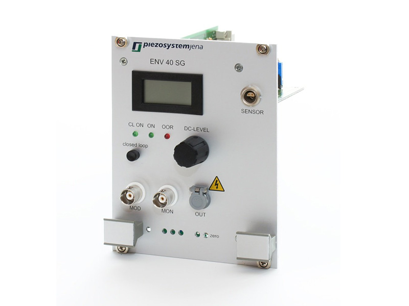
The ENV controller system is a modular configuration within a 19-inch housing, that is designed to work with a ENT series power supply. For each application you can combine one or more amplifier modules with different characteristics. A completed system is tailor-made for the application.
Each amplifier module has it’s own display showing output voltage. If used with a measurement system and closed loop module, it displays the calibrated motion. Different modules for closed loop and PC connections are available. The front of each amplifier module includes the input and output connections, the display, and the potentiometer for manual control.
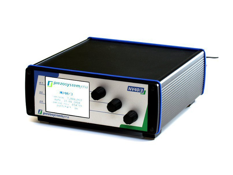
The NV40/3 piezo amplifier was designed for controlling low voltage piezo elements. It includes a voltage amplifier, a display and a PC-interface. The high-resolution display shows the voltage of the actuator, along with the mode of operation and the temperature inside the amplifier.
This amplifier also provides the opportunity to control the piezo element via analog modulation input or RS232. The actuator voltage can be viewed via the monitor output.
Due to the very low voltage noise of the output current, only 0.3 mV rms, the amplifier is ideally suited for positioning applications with sub-nm resolution. Special protective circuits prevent voltage spikes when switching the unit on and off and consequently avert any overload caused by overheating or short-circuiting. This soft-start ensures an actuator-safe activation of the system.
Due to its design and compact casing, the amplifier is recommendable for R&D and engineering applications.
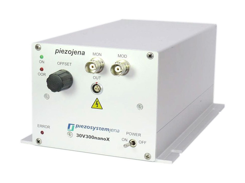
The 30V300 piezo controller is especially made for controlling high precision, flexure guided piezo actuator stages used in highly dynamic nano-positioning tasks. One of the key features is the 300 mA permanent output current which enables the 30V300 piezo controller to drive piezo actuator elements with the highest frequency.
The 30V300 series is available in 3 different casing styles for highest flexibility in use. The robust metal casing is available in a table top version, as an industrial rack mount 19“ version, and in a screw-slot mounting version. These various options support flexibility in use and industrial compatibility.
The 30V300 piezo controller series displays a superior voltage noise of the output signal of only 0.3 mV. This guarantees the achievement of nearly unlimited positioning resolution of piezoelectric actuators, down to a single step resolution in the sub-nanometer range. The 30V300 CLE is equipped with an integrated sensor controller module which allows the highly dynamic control of piezoelectric elements equipped with an integrated feedback measurement system.
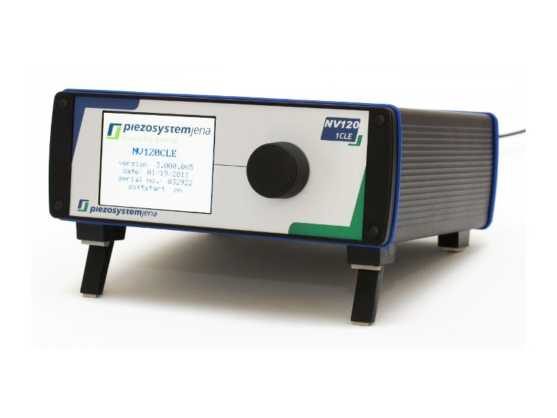
The NV120/1 and NV120/1 CLE piezo amplifiers are engineered to meet the highest standards of accuracy and dynamics for high-resolution piezoelectric actuators.
These amplifiers provide a permanent output current of 120 mA, with a signal noise of <0.3 mV @ 500 Hz. It achieves position resolution in the sub-nm range in addition to a settling time in the microseconds range.
The NV120/1 piezo controllers are designed to be compact table top systems in a rugged metal housing. To accommodate use in laboratory conditions, the amplifiers have a dimmable TFT display.
For user flexibility various control options are included. A manual control, as well as an analog control, and various digital interfaces are available. The NV120/1 has two types of amplifiers. The NV120/1 is intended for actuators without an integrated measurement system.
The NV120/1 CLE has automatic sensor identification – the integrated ASI-functionality. It is designed for use with piezo actuators that have an integrated measurement system. It can be either a high-resolution strain gauge sensor or a non-contact capacitive sensor.
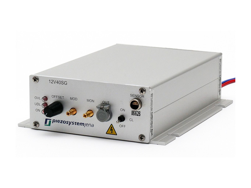
The 12V40 controller is designed for piezoelectric actuators used in nano-positioning tasks for industrial applications. Different types of casing, with and without screw slots, and a 19″ rack mount version are available.
The 12V40 requires a main supply voltage of 12 V DC. The piezo controller offers the user the choice to control a piezoelectric element manually or via analog modulation input with a signal of 0 to 10 V DC – with a nearly unlimited step resolution. To support industrial use, all operational elements from the front panel are also available on the rear panel. All sockets are also available on the back so that the amplifiers can be easily integrated into an OEM product line. The output voltage can be supervised on the monitor output. Special circuits are integrated to protect the piezo element from voltage spikes and excessive voltages.
These amplifiers are well suited for sub-nm positioning tasks due to a very low voltage noise of only 0.3 mV rms.