Resolution
The resolution specifies the smallest possible measurable movement of the actuator. It is almost infinite and depends on environmental influences, drift, and mechanical factors. PZT’s have a nearly unlimited resolution.
The resolution is typically determined by the noise of the applied voltage signal. High resolution piezo amplifiers from piezosystem jena come with a typical signal noise of < 0.3 mV@500 Hz. For more information read piezo theory.
ASI/ASC
ASI and ASC are new functionalities of the piezoelectric systems offered by piezosystem jena for automatic sensor identification and the ability to interchange single parts of a system (actuator or electronic) without a new calibration procedure. These systems can remain on location and in the field without any time or money being spent for additional shipping.
ASI function = Automatic Sensor Identification
The ASI function allows you to exchange the same type of actuator and use it with the same amplifier. Actuators for an ASI compatible amplifier are equipped with an identification circuit connected to the actuator. This feature assures a full sensor calibration. New calibration is no longer necessary (valid only for standard calibration).
ASC function = Automatic System Calibration
In addition to the ASI function, ASC provides even more functionality for our customers. The integrated circuit built into a closed loop actuator also contains the parameters for calibration and other information such as:
Motion
Name
Axis
Serial number
PID-control and filter setting
Thus, the electronics can not only identify the actuator, but also its calibration data. When the actuator is exchanged to a different type, the electronics do not need to be recalibrated and the system immediately works at its peak performance. A full function generator setup, containing amplitude, offset, frequency, and so on, is stored in the id chip. Thus, the setup is once again active after switching the electronic.
Blocking Force
The maximum force an actuator can generate if blocked between two walls (with an infinitely large stiffness). This generated force specifies the blocking force
Bi-directional Active Manner
Due to the inability of the SMCA (stacked multilayer ceramic actuator) to generate pull forces, state-of-the-art piezoelectric driven nano-positioning actuators show different kinds of behavior depending on the sense of direction of their stroke. Hence, the resulting forces in the push direction are determined by the high force generation of the actively controlled smca. The pull force is determined by the weak spring reset force of the passive acting flexure hinges. Both result in a push/pull-force ratio of up to 10. The dynamical performance, load capacity, and robustness of the whole nan-opositioning assembly are limited by the behavior of the weaker sense of direction. The piezosystem jena sophisticated gear design operates in a bidirectional active manner which reduces the push/pull-force ratio to up to approx. 1:1 (without affecting the trajectory). Both stroke vectors of the nano-positioning stage are controlled by the high pressure force generation of the SMCA.
CE/EMV Certification
All products from piezosystem jena are CE certified and all electronic systems are proofed based on German EMV certification test procedure.
Closed-Loop Operation
The displacement of the actuator is corrected by a measurement system compensating for non-linearity, hysteresis, and creep. piezosystem jena typically uses strain gauge or capacitive feedback sensor systems. Elements which are equipped with a sensor system have the suffix SG (strain gauge) or CAP (capacitive) in their product name.
Drift/Creep
Creep is a dimensional stabilization over a period of time. A step change in the applied voltage will produce an initial motion followed by a smaller change in a much longer time scale. To overcome the effect of drift, the piezo system has to be equipped with an external feedback control measurement system, like strain gauge or capacitive sensors.
Piezo Positioning
Piezo positioning technology has some important advantages over electrical driven actuators:
- Can offer resolution within the nanometer range
- Every single changing of the applied signal causes an electrical field changing. This is the reason for short reaction time and fastest positioning (e.g. piezo scanner)
- In combination with closed loop feed back control and offers high repeatability and long terms stability with sub nanometer accuracy
- They are without mechanical play by using flexure hinges guided systems for the nano-positioning system
- They are without wear, because a piezo actuator does not have moving parts. Piezo elements can be used under vacuum and also in cryogenic conditions after preparation
Hysteresis
Actuators show a typical hysteresis behavior due to the ferroelectric nature of PZT ceramics. It occurs when the driving direction is reversed. To overcome the effect of hysteresis, the piezo system has to be equipped with an external feedback control measurement system, like strain gauge or capacitive sensors.
Lens-Flex-Adapter
MIPOS series: Lens Flex-Adapters improve handling and compatibility
What is important to know about vacuum applications?
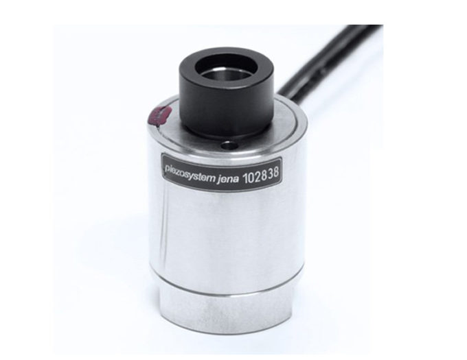
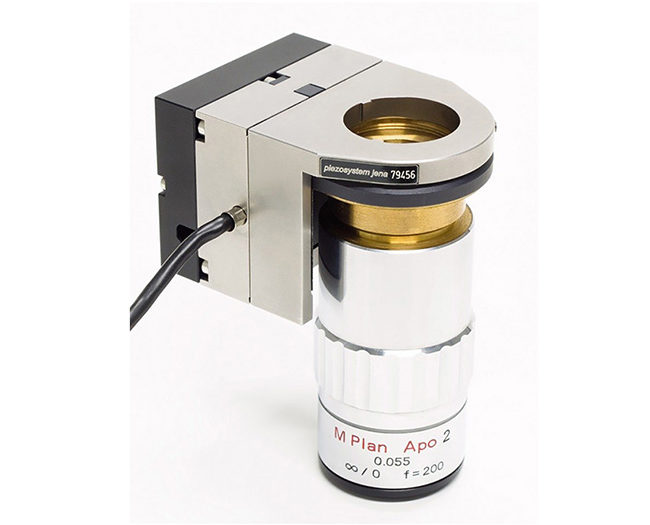
piezosystem jena has made major improvements to its well established MIPOS series by introducing the new Lens Flex-Adapter mechanism. This technology allows the easy and fast exchange of microscope objectives compatible with a variety of thread sizes from Zeiss, Leica, Nikon, Olympus, and others.
The new Lens Flex-Adapter makes it possible to combine objectives and microscopes from different manufacturers with ease.
The Lens Flex-Adapter mechanism makes the interchange of objectives both simple and accurate due to the use of an exchangeable thread adapter in sizes ranging from W0.8 x 1/3” up to M32 x 0.75. Its innovative design avoids extra forces while the objectives are being changed by not allowing the material to merge. Lens Flex Adapters are available individually as well as a set of six thread type adapters for the the combination of different microscopes and objectives.
The MIPOS series actuators were developed for the fine adjustment of micro objective lenses. They provide a wide range of motion from 20 µm up to 500 µm. Their position accuracy and resolution are extraordinarily high. The MIPOS is the perfect upgrade for modern microscopes.
Key Features:
Focus range up to 500 µm
Easy assembling and disassembling due to the Flex-Adapter mechanism
Available Lens Flex Adapter – thread types:W0.8×1/36” (RMS), M25x0.75, M26x0.75, M26x1/36”, M27x0.75, M32x0.75
Parfocal Spacer Rings for tube extension
Compatible with both standard and inverted microscopes
Micro-positioning
This term stands also for the highest level of accuracy and precision in the positioning technology. Whether in the medical sector, the optics & laser technology or pick&place Automization, smaller and more accurate structures require appropriate positioning systems. The piezo technology is ideal suited for micropositioning because of its physical properties of the piezo electrical effect. The advantage of the piezo electrical effect is used by piezosystem jena for driving solution in tools and instruments for the area of nano and micro/fine positioning applications. The accuracy of typical <1 nm in the position is based on the high dynamic behavior of piezo based positioning systems. They are ideally suited for a wide range of further applications, they are not mentioned here.
Non-linearity
The relation between applied voltage and stroke of a piezoelectric actuator is not linear because of e.g. hysteresis. Therefore in open loop systems, doubling the voltage does not exactly mean to double the stroke.
In closed loop systems, linearity is introduced by the position feedback sensor which corrects hysteresis and drift. The remaining non-linearity is usually under 0,1 %.
Open-Loop Operation
The actuator is operated without a measurement system. Displacement is approximately correlated to the drive voltage. Non-linearity, hysteresis, and creep are not compensated for.
Piezo
The word „Piezo“ originated in the greek language (piezein) and means something like „press“ or „squeeze“. The term „Piezo Effect“ is used to describe the electrical current which is generated by putting mechanical pressure onto a certain material. The „inverse Piezo Effect“ goes the opposite direction. Here, a current is applied to the material and in turn the material expands and performs a mechanical motion. All materials which have such properties are called „piezo“ or piezo materials. Today, specially produced piezo ceramics are used to harness the Piezo Effect. At piezosystem jena, these ceramics are used as actuating material (with the inversive Piezo Effect).
Cryogenic Application
The piezo effect itself depends on the temperature. The effect decreases with decreasing temperature at a rate of approx. 0.4% per Kelvin. In the temperature range of liquid nitrogen (ca. 77 K) the expansion due to the piezo effect will be about 20-30% of the expansion at room temperature.
In principle, piezoelectrical actuators can work at very low temperatures, such as the temperature of liquid Helium (4 K).
All systems ordered with the vacuum compatible option can be used in the cryogenic region. Please note that the original motion of the PZT is reduced when used at low temperature.
Piezoelectric Effect, Inverse Piezoelectric Effect
The result of external forces to a piezoelectric material is positive and negative electrical charges at the surface of the material. If electrodes are connected to opposite surfaces, the charges will generate a voltage U.

d – piezoelectric module; parameter of the material (depending on the direction) C – electrical capacitance
By generating forces F to the piezoelectric material, the volume (bulk) of the material will be approximately constant. The Curie brothers first discovered piezoelectricity in 1880. It was found by examination of the crystal TOURMALINE. Modern applications of the piezoelectric effect can be found in sensors for force and acceleration, musical discs, microphones, and also in lighters. An applied voltage to a piezoelectric material can cause a change of the dimensions of the material, thereby generating a motion. Lippmann predicted this inverse piezoelectric effect and the Curie brothers were the first to experimentally demonstrate it. The first applications were in ultra sonic systems for underwater test and also underwater communications. For actuators, the inverse piezoelectric effect was applied with the development of special ceramic materials. Materials for piezoelectric actuators are PZT (lead-zirconium-titanate). For the electrostrictive effect the materials used are PMN (lead-magnesium-niobate). When speaking about actuators, the phrase “piezoelectric effect” is often used – strictly speaking, it should be called “inverse piezoelectric effect”.
Piezo-Element
These terms are used colloquially, when we talk about a complete piezoelectric actuator system or the full piezo ceramic element. It does not matter, whether the piezo element is used as an actuating element or as a sensor. In any case, this element uses the piezoelectric effect or is used because it can exploit the piezoelectric effect. If we talk about a piezo element, then usually the fully sintered ceramic is meant as a finished component. However, individual piezoelectric components are often referred to as piezo crystals.
Piezo Products
The term “piezo” comes from the Greek word meaning “push or press” and describes the generation of an electrical voltage signal due to the deformation of a piezoelectric material. The term describes all products, which implement this effect. piezosystem jena uses the piezo effect as an actuating element for positioning purposes. The design varies according to use and application. When we consider the actuator used by piezosystem jena, then we speak of the inverse piezoelectric effect.
Piezo Stage
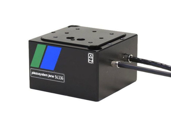
This term is often used for a piezoelectric element based stage where a actuator is used as the driving element. Usually the piezoelectric actuator comes with an assembled so-called “table top plate” or “desk top plate” which is equipped with a number of pin hole patterns or threading holes. This allows the user of the piezo stage to install components without the risk of damage to the piezo drive. piezosystem jena offers a complete range of piezo actuating stage systems. X-axis, XY-axes, 3D micro positioning (multi-axis) and nano-positioning elements, piezo based tip/tilting platforms and Z-axis piezo stages are all available by default.
Resonant Frequency
Piezo actuators are oscillating mechanical systems characterized by the resonant frequency. The resonant frequency is determined by the stiffness and the mass distribution (effective moved mass) within the actuator. Actuators from piezosystem jena reach resonant frequencies of up to 50 kHz.
All values given in the table of the catalog are based on the average of measurement values of each part of the given series.
Piezo elements represent an oscillating system with a certain resonant frequency. In most cases, the resonant frequency is reduced during the assembling and mounting of loads. To prevent any damage, piezo elements should only be used at up to 80% of the resonant frequency. The mentioned resonant frequency can be found on data sheets, in catalogues, or on our website and is only valid, unless otherwise stated, for unloaded piezo elements and actuators.
Sensors for Piezos
Differences between capacitive feedback sensors and strain gauge feedback sensors for closed loop systems.
What are the differences between closed loop systems with capacitive feedback sensor and those with strain gauge feedback sensor?
Piezo systems with capacitive sensors attain a better resolution (sensor resolution 1 nm), non-linearity (typ. 0.05%), and repeatability. Capacitive systems are the best choice for applications that require good long time stability. Normally these sensors are arranged in the actuator between the fixed-point and the drive side. Thus, they register the whole mechanical assembly and control the position with nanometer and sub-nanometer precision.
The resolution for open loop actuators depends on the small signal behavior (noise) of the controller. Controllers from piezosystem jena have a minimal noise down to < 0.15 mV. The resolution for SG (strain gauge) sensors depends on the noise of the closed loop electronics including the sensor signal. Usually the resolution of a SG system is 10 times higher as for the open loop system. But for most of our elements the resolution of a SG system is still better than 1 nm. For detailed values please check the datasheet of the specific stage.
Results:
CAP – Advantages
High measurement accuracy, optimal for long time applications
Good values regarding non-linearity, repeatability, and resolution
Cross motion is compensated e.g. for XY systems
CAP – Disadvantages
Actuators often have a bigger footprint
Bandwidth max. 1 kHz
Higher costs than systems with SG sensor
DMS/SG – Advantages
Very compact size
Higher bandwidth of up to 5 kHz
More cost effective than the CAP system
DMS/SG – Disadvantages
No high long-term-stability
Resolution depending on system – in most cases below 1 nm
Cross motion is not compensated for XY-Elements
Softstart
What does “softstart” mean?
Softstart is a procedure that initializes your complete system consisting of a piezo actuator and an amplifier. After powering on, the amplifier starts to apply voltage until it has reached the full voltage range, and then cycles it back to zero. This way the piezo actuator moves from the minimum position to the maximum and back.
Piezo actuators in the nanoX, nanoSX, nanoSXY, and nanoMIPOS series, as well as some of the piezo tilting systems, start their cycle from the middle position to the maximum and then to the minimum (zero position). This cycle takes approx. 3 seconds. After this process the system is ready for operation.
Why do I need “softstart”?
The inverse piezoelectric effect is a solid state phenomena that results from the arrangement of the polarized unit cells depending on the applied electrical field. During long term storage, depolarization may occur so that the dielectric field strength within the multilayer piezo ceramic decreases.
An abrupt application of high voltage may cause the piezo actuator to short circuit. To avoid this risk, the automatically launching softstart procedure re-polarizes and refreshes the piezo ceramic.
Can “softstart” be deactivated?
Yes, if required the softstart can be switched off. Deactivating the initializing procedure is recommended for applications where the piezo actuator is operated daily or where the actuator’s full stroke would cause clashes in the application set up.
Switching off the softstart is realized via software or by changing the jumper position. Please inform us about your requirements when ordering.
Stiffness
The stiffness is the spring constant. It is an important parameter for characterization of the resonant frequency and generated forces.
Repeatability
The repetition accuracy is designated by the error, which arises if the same position is approached from the same direction again and again. It contains neither hysteresis nor drift. The repeatability for each calibrated system is shown in the calibration protocol. All values given in the table of our catalog and the data sheets are based on the average of measurement values of each part in the given series. More Information is available under piezo theory.
Piezo Principles Topics
- 1) Piezoelectric Effect
- 2) Design
- 3) Properties and Performance
- 4) Static Positioning
- 5) Dynamic Movements
- 6) Lever Transmission Systems
- 7) Simulation of Dynamic Properties
- 8) Closed Loop Systems
- 9) Measurement Systems
- 10) Electronics
- 11) Lifetime and Reliability
- 12) Guidelines for Usage
- 13) High Power Piezos
- 14) Piezo Shakers
- 15) Piezo Shock Generators
