10. Electronics – Needed for Piezo Actuators
In section 3.3. we mentioned that the sensitivity of piezoelectric actuators is only limited by the voltage noise of the power supply. If a power supply has a noise given by ?U, the mechanical motion ?X, determined by this noise will be:
Where U is the current voltage to the piezoelement, Δl is the expansion for the voltage U.
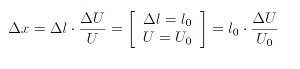
Power supplies from piezosystem jena are developed and optimized especially for piezoelectrical actuators. So they have excellent noise characteristics, which allows positioning in the nm range. (see Figure 10.1.1.)
Example Number 23
The power supply NV 40/3 CLE is suited for 3 channels (e.g. a TRITOR element for 3D positioning). This device has a voltage noise of < 0.3mV. For a maximum output voltage of 150V this is a dynamic range of < 2·10-6. For a piezoelement with a motion of 50µm we yield a mechanical noise of 1nm.
10.2. Current
For dynamical motions, all power supplies from piezosystem jena have a modulation input for each channel. So it is possible to generate oscillations given by a function generator via the modulation input. The electrical properties of piezoelectric actuators are such that they act as capacitors with a high inner resistance of typically 109Ω.
Typical values for the capacitance are:
High voltage actuators: 60nF
Multilayer-low voltage actuators: 1800nF
For static and quasi-static applications, the current consumption does not matter. Because of their high resistance piezoelectric actuators do not need current to hold a position. They can also hold a position after separation from the power supply (Please consider the safety instructions! We strongly recommend not to do this, the actuator keeps the stored voltage and this is extremely dangerous). For dynamic applications we have to consider the problem of charging and discharging the capacitance C. The current I that is needed for the actuator is:

dU/dt – slope of the voltage (in V/s)
The amount of the current needed can be very high for dynamic operations, so the slope of the voltage is often limited by the maximum current of the amplifier. For a dynamic operation with a sinusoidal function, the maximum current Imax is determined by:

Imax – peak current required for sinusoidal operation (in A)
Upp – peak-peak driving voltage (in V)
f – frequency (in Hz)
C – capacitance of the actuator (in F)
During dynamic operation, a typical class-A amplifier has to provide energy only while charging the piezo. This energy, that has to be provided by the power supply, is then dissipated into heat during the discharging process. Averaging the forward charging current over the whole period of motion gives the average current:

10.3. Electrical Power
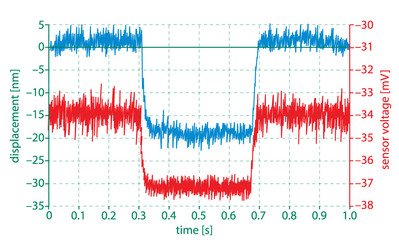
Because of the high current that is needed for dynamic applications, the electrical power needed can also be high. The average power Pav for unipolar, harmonic operation with frequency f of a piezo element with capacitance C will be:
Pav – average power (in W)
Upp –peak-peak driving voltage (in V)
f – frequency (in Hz)
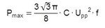
The peak power Pmax is the local maximum of the time dependent electrical power. For unipolar, sinusoidal operation this results in:
Example Number 24
The piezo element PAHL 18/20 is suited for high loads and it has a capacitance of 7 µF (for small field strength). This value can rise up to 14 µF for large operating electrical fields. For an oscillation of 1 kHz an actuator with 7 µF capacitance requires a current of 3.3 A. For a capacitance of 14 µF one needs a current of nearly 7 A. The output power will also increase 2 times and it will reach 650 W. For such electrical power, heating of the actuator should be considered (see also section 10.6 power loss).
10.4. Switched Regime – Oscillations with Rectangular Form
Due to their properties piezo elements can work in a switched regime (e.g. for valve applications). For the voltage supply we use an electronic switch. If a short pulse is given to an actuator, the output voltage (also the voltage at the actuator) U(t) will rise depending on the time t, the capacitance of the actuator C and the inner resistance of the power supply Ri.
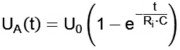
U0 – maximum output voltage of the supply.
If the inner resistance of the power supply Ri is small enough, the output voltage increases very quickly. This can be realized faster than the minimum rise time of the actuator, which is determined by the resonant frequency (see also section 5.1). That´s why the actuator is not able to expand faster. In such case the actuator will expand corresponding to the given electrical charges and so the expansion will reach an intermediate state smaller than the maximum output voltage U0 of the power supply. In this way it is possible to generate a continuing signal form with an electrical switch by a series of charging and discharging pulses.
10.5. Coupling Factor
The mechanical energy Wmech stored in the piezoelectrical material is created as a consequence of applied electrical energy. The electromechanical coupling factor k33 describes the efficiency of the conversion of the electrical energy Welectr into stored mechanical energy Wmech.
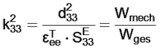
It can also be seen that the coupling factor depends on the direction and the parameters of the material. The formula is given here for the longitudinal effect.
The above mentioned formula is valid only for static and quasi-static conditions; power losses (e.g. by warming) are not included. The electrical power, which is not converted into mechanical energy (as expressed by the coupling factor), is given in form of electrical charges. These charges are returned to the power supply while unloading the actuator’s capacitance.
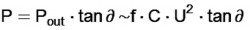
10.6. Power Losses – Dissipation Factor
In the static regime the actuator stores energy W = ½ · C · U2. While unloading the piezoelements most of the electrical energy returns to the power supply. Only a small part will be converted into heating the actuator. These dissipation losses are expressed by the dissipation factor, the tangent of the loss angle δ.
Example Number 25
Let us consider the data given in example 24 (section 10.3). For the modulation of the piezoelement PAHL 18/20, an electrical power of approximately 1000W is necessary. The dissipated energy will be in the order of 50W, concentrated to a volume of 2ccm. After a short time, heating will bring the actuator in the region of the Curie temperature and the piezoelement will stop working. In such cases effective cooling will be necessary.
Power Optimization
In some cases the choice of power supplies and piezo elements can be optimized for minimum power requirements. It might be better to use a longer stack with a lower operating voltage.
Piezo Principles Topics
- 2) Design
- 10) Electronics
- 14) Piezo Shakers