7. Simulation of Dynamic Properties – Transformation of Electrical and Mechanical Properties
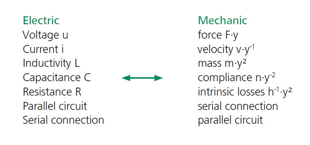
The piezoelectrical effect describes the electromechanical coupling behavior of ferroelectrical materials. A theoretical model of electromechanical transducers is given with an electromechanical network. This network consists of electrical and mechanical components, which are connected via a specific four-pole circuit with the coupling factory.
Using this model makes it possible to simulate the dynamic behavior of piezoelectric actuators. The equivalent electrical circuit of piezoelectrical actuators can be determined with the help of an electrical impedance analyzer. With the equivalent electrical circuit, it is possible to simulate the dynamic behavior of the corresponding actuator system. The electrical model can be implemented in standard simulation programs and, thus, whole systems, including the power supply and a closed loop control circuit, can be simulated.
In the case of piezoelectrical transducers, the components of the theoretical networks are: the electrical free capacitance Cb, the mechanical elements compliance n (mechanical stiffness n-1), effective mass m and the intrinsic mechanical losses h. Due to the reciprocal network characteristic with the cupling factor y, the following relation can be given:
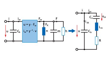
A transformation of the mechanical components to the electrical side of the four-pole network leads to the model of the equivalent electrical circuit of piezoelectrical actuators (Figure 7.1.1.).
Mit:


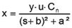
The representative electrical circuit gives a linear approximation of the electromechanical system. The characteristic equation of this network is similar to the characteristic equation of a simple spring-mass-oscillator. If a force F is applied to a mechanical spring with the stiffness n-1, the displacement x is given with x=Fk·n. With the given coupling relation, the equivalent equation for the electrical network is:
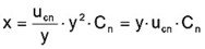
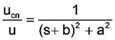


Therefore the characteristic equation for the mechanical dispplacement of piezoelectrical transducers can be determined from the equivalent electrical circuit:


As mentioned before, the model of the equivalent electrical circuit corresponds to a linear approximation of the real coupling behavior of electromechanical transducers. This model includes neither the piezoelectrical hysteresis nor the creep and saturation of polarization. Further restrictions of this model are given with the special characteristic of the piezoelectrical material parameters. All specific material properties (e.g. compliance, capacitance, piezoelectric coefficient) are dependent on the the applied electrical field. This dependence is not to be considered by the linear model.
Example number 20
We tried to find a simulation model for our actuator PU90. His model should be able to calculate the dynamic behavior of this element with different additional masses.
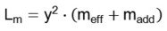
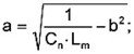
meff is the effective moved mass of the actuator system without an additional load and madd is the additional mass. To calculate Lm for any loads, it is necessary to find the values for y and meff. This can be done with two measurements on an electrical impedance analyzer (with different loads). We made four measurements to reach a higher reliability in our model.
From these measurements, we obtained the following values for the model of the actuator system PU 90:
meff=89.8 g; y=2.12 m/As; R=38.92 Ω; Cn=171 nF; Cb=1.56 µF
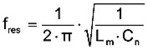
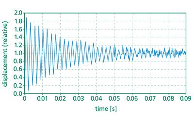
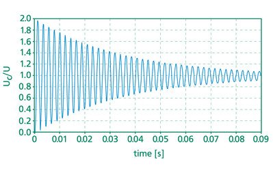
With this model we calculated the resonant frequency with respect to an additional load and we simulated the response of this actuator to a voltage step. We proved our model with some additional measurements which were done with the aid of an interferometer displacement sensor. The results are given in the diagrams. (Figure 7.1.2./3./4.)
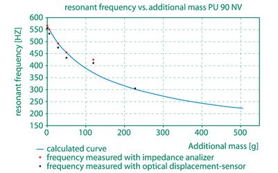
Figure 7.1.2. calculated resonant frequency of the actuator PU 90 with respect to an additional load.
Simulation models of several piezosystem jena actuator systems were made. With these models it is possible to determine significant mechanical parameters for the dynamic use of piezoelectrical actuators. In this way, custom-designed actuator systems can be realized much easier and more efficiently.
7.2. FEM Optimization
A lot of applications require special mechanical properties to be considered from the beginning of the development. Additional loads to be moved dynamically require a complex optimization process of the stage. Using only formula 3.5.1. or 6.2. does not allow one to develop optimized stages. The full construction should be designed using FEM calculations. With our extensive experience in FEM calculations we can optimize more accurate parameters as stiffness, minimum tilting properties and others.
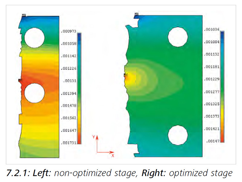
The following 2 pictures show how to optimize a stage for minimum cross motion. Cross motion occurs if one axis is moved (here the y-axis) but the other axis still shows a small motion. This cross motion is a result of a non-optimized construction, material imperfections and other factors.
In figure 7.2.1 on the left the stress inside a stage is shown while the stage moves in y axis. Occurring tensile forces in x-axis leading to a tilt of 67µrad (calculated by FEM analysis) because of the above-mentioned imperfections. On the right, the holes for mounting the stage are replaced; optimized for a minimum x tilt. The result is a tilt of 6,6µrad, which is 10 times smaller than the non-optimized stage in figure 7.2.1. piezosystem jena uses its extensive experience in FEM calculations to develop special products optimized for the very special needs of your particular application.
Piezo Principles Topics
- 2) Design
- 10) Electronics
- 14) Piezo Shakers