4. Static Positioning
Static Behavior of Piezoelectric Actuators
To generate an expansion in a piezoelectric actuator, the ceramic material must be pre-polarized. The majority of the dipoles must be oriented in one direction. If an electrical field is now applied in the direction of the dipoles, (here the z direction) the actuator will show an expansion in the direction of the field (longitudinal effect) and will show a contraction perpendicular to the field (transversal effect).
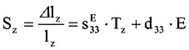
The motion is expressed by the equations:
Longitudinal Effect
Transversal Effect
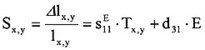
S – strain, relative motion, T = F/A – mechanical tension pressure (e.g. caused by external forces), sii – coefficient of elasticity (reciprocal value of the Young’s modulus), Δlz – expansion of the actuator in z dimension, lz – length of piezoelectrical active part of the actuator, cF – stiffness constant of the external spring for pre-load, cT – stiffness of the actuator.

Piezoceramics are pre-polarized ferroelectric materials; their parameters are anisotropic and depend on the direction. The first subscript in the dij constant indicates the direction of the applied electric field and the second is the direction of the induced strain.
Typical coefficients are:
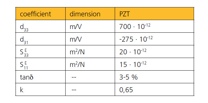
The negative sign represents the contraction perpendicular to the field. Typically, high voltage actuators are made from “hard“ PZT ceramics and multi-layer low voltage actuators are made from “soft“ PZT ceramics.
For the sake of simplicity, if not otherwise mentioned, from now on we will refer to the longitudinal piezoelectrical effect, however all relations can be written in the same manner for the transversal effect.
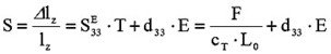
The first term of the equation (4.0.3) describes the mechanical quality of an actuator as a spring with a stiffness cT. The second term describes the expansion in an electrical field E.
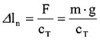
4.1 No Voltage is Applied to the Actuator, E = 0
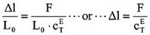
The actuator is short-circuited. Formula (4.0.3) becomes S = Δl/L0 = s33 · T. The deformation of the actuator Δl is determined by the stiffness of the actuator cTE because of the action of an external load with the pressure T, so it becomes “shorter“.
The stiffness cTE of an actuator can be calculated by taking into account the stiffness of the ceramic plates. This approximation assumes that the adhesive between plates is infinitely thin. Monolithical multi-layer actuators perform well in this respect, giving stiffness on the order of 85% – 90% of the stiffness of the pure ceramic material. Especially for high voltage actuators, the stiffness of the metallic electrodes and the adhesive have a large influence on the stiffness of the stack.
Example number 13
On a stack with a stiffness of a given cTE operates at an external force of F = 70N, using formula (4.1.1) it is easy to calculate the compression of a stack of 1µm.
4.2 No External Forces, F = 0
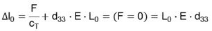
The maximum expansion depends on the length of the stack, on the stack, on the ceramic material and on the applied field strength.
Example number 14
Let us consider a multi-layer stack with the following parameters:
Piezoelectrical constant d33 = 635·10-12m/V
Active length L0 = 16mm
The thickness of a single plate is 100µm. The operating voltage is 150V. The field strength is E = 1.5kV/mm.
4.3. Constant External Loads, F = CONSTANT
However, the expansion l0 due to the applied voltage will be the same as when an external force is not applied (see formula 4.2.1.).
In cases where excessively high external forces are applied, depolarization may occur if there is no applied electrical field. This effect depends on the type of ceramic materials used.
This polarization may be reversed if an electrical field is applied.
However the depolarization can be irreversible if the external forces have exceeded the threshold limit for that material. Damage to the internal ceramic plates may also occur. Therefore it is important to respect the given data for the relevant materials.
Standard actuators from piezosystem jena with a cross section of 5 x 5mm² show depolarization effects for external loads > 1kN. Please see the given parameters in the specific product data sheets.

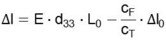
4.4 Changing External Loads and Forces, F = f (Δl)
As an example of changing external forces, consider attaching an external spring. Because of the spring’s nature, the forces F, operating to the actuator, increase with the increasing displacement. If the external forces can be expressed as F = -cF·ΔL (cF stiffness of the spring) we get the following expansion of the actuator:
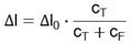
A part of the motion will be needed to compensate the external forces, therefore the final motion becomes smaller (see also figure 4.4.1.).
If the stiffness of the actuator and the stiffness of the external spring are equal, the actuator will reach only half of its normal motion.
Example number 15
The actuator PA 16/12 has a stiffness of cT = 65 N/µm. The motion l0 without external forces is 16 µm. This actuator is assembled in a housing with a pre-load stiffness cF = 1/10cT. In comparison with formula (4.4.2.) the motion will decrease to 14.54 µm. If the stiffness of the pre-load is increased to 70% of the stiffness of the actuator cF = 0.7 cT = 46 N/µm, the motion will reach only Δl = 9.4 µm.

Using equation (4.4.2.) we can calculate the effective forces, which can be reached with an actuator operating against an external spring.
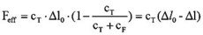
Δl0 – motion without external loads (µm), Δl – motion under external loads (µm).
Example number 16
Again, we will use the actuator PA 16/12. For motion without external load l0, the stiffness is cT = 65N/µm. This actuator is working against a spring with a stiffness cF = 64 N/µm. In this assembly the actuator will reach an effective force of 516 N. When it operates with an external spring with a stiffness of 500 N/µm, it will reach an effective forces of F = 920 N.
An external variable force operating with an actuator will decrease the full motion.
Integrated pre-loads of piezoelectrical actuators are external forces. The value of the integrated pre-load often reaches 1/10 of the maximum possible load of the actuator. That is why the shorter expansion of pre-loaded actuators is very low.
But pre-loaded actuators can work under tensile forces. They are well suited for dynamical applications.
4.5 Blocking Forces, DELTA L = 0
The actuator is located between two walls (with an infinitively large stiffness). So it cannot expand (see formula 4.2.1.):
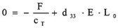

This force is called a blocking force of an actuator.
Operating against external spring forces, actuators show the following behavior of the generated forces in dependence on the expansion. This stress diagram is valid for typical actuators used by piezosystem jena.
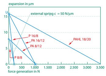
The cross over with the x-axis indicates the blocking force. The cross over with the y-axis shows maximum expansion without external forces. Also shown is the curve of an external spring. The cross over of this spring load line with the curve of the actuator gives the actual parameters, which can be reached with this actuator operating against a defined spring.
An actuator can generate the maximum mechanical energy if it is operating to an external spring with a stiffness of half the actuator stiffness (cF = ½·cT). In this case the actuator reaches only 67% of its normal (without external forces) expansion.
Example number 17
An actuator of the type PA 16/12 operates to an external spring, without loads the actuator reaches a motion of 16µm. A generated force of 320 N is demanded. What motion can be reached under such conditions?
Answers:
Look at the diagram, the vertical line beginning at the point of 320 N crosses over to the actuator´s PA 16/12 curve. The horizontal line, beginning at this point of the cross over will end in the value of the possible motion, approximately 12 µm. The same result can be calculated using (4.4.3.). For the real expansion l under external spring forces we yield from (4.4.3.) Δl = Δl0 – Feff / cT. The stiffness of the actuator is cT = 85N/µm. Thus the result is Δl = 12,2 µm.
Please note:
In practice an infinitely stiff wall or clamping to the actuator cannot be realized. For this reason an actuator will not reach its maximum theoretical force in reality. Please note also that if the actuator should generate its blocking forces it will not show any motion.
Piezo Principles Topics
- 2) Design
- 10) Electronics
- 14) Piezo Shakers