9. Measurement Systems
Introduction
The influence of the ferroelectrical hysteresis and the effect of the time dependent creep limit the best mechanical parameters of piezoelectrical actuators. In a large number of applications these effects do not play an important role. For other applications it is advantageous to implement a closed loop system. In a closed loop system the motion of the actuator will be measured and any unwanted changes from the given position will be corrected by the closed loop electronics.
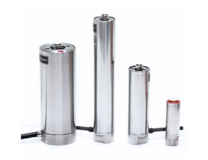
piezosystem jena uses different types of measurement sensors:
• Strain gauge
• Inductive (LVDT)
• Capacitive
They can be integrated in nearly all piezoelectrical translation stages from piezosystem jena.
Capacitive or LVDT sensors should be used for systems needing the highest accuracy and/or dynamics. In some cases it is necessary to measure the displacement somewhere outside of the actuator. To provide the best performance for special requirements it is necessary to know the fundamental properties of the different sensor systems. In all cases it must be taken into account that, for µm and sub-µm accuracy, the full system has to be optimized (actuator, sensor, electronics, environmental conditions, etc.).
9.1 Resolution
The piezoelectrical effect is a real solid state effect. In theory there is no limitation to the resolution; an infinitely small change in the electrical field gives rise to an infinitely small mechanical displacement. The real world offers some limits in resolution, which are caused by electrical, mechanical, acoustic and thermal noise.
Mechanically:
The mechanical resolution is determined by the design of the drive. Actuators from piezosystem jena are made with flexure hinges. Due to this construction principle no mechanical play arises, whereby the mechanical resolution is unlimited.
Electrically:
During operation the resolution indicates how much the actuator moves if no motion is indicated i.e. the output voltage of the amplifier is to remain constant. This resolution is determined by the noise of the output voltage. Here only the frequency range of the output voltage is taken into consideration, which the actuator is able to follow.
Usual actuators with lever transmission of piezosystem jena have a resonant frequency between 200Hz and 750Hz, so the output voltage is measured only up to this frequency. Frequencies above this range can not be converted into a motion by an actuator. A voltage noise of 0,3mV means that the actuator has a resolution of 0,2Nm, related to a total travel of e.g. 100µm @ 150V (total voltage range: -10 … +130V).
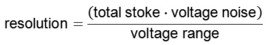
For the resolution in the closed loop mode the noise of the measuring system must be additionally considered. Therefore the noise of the output voltage in the closed loop mode is measured. This value depends on the used actuator, the measuring system, the adjusted control parameters and the amplifier. The comutation of the resolution is made according to the formular indicated above.
The data for non-linearity related to the position, repeatability and lower and upper voltage limit are provided on the calibration report sent with the system.
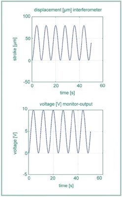
To measure the resolution of a closed loop system we used a PX 100 with capacitive sensor and a power supply NV 40/3 CLE. The investigations were done considering best environmental conditions as mentioned above. The element was driven with a square function of approximately 40mV amplitude.
In figure 9.1.1. and 9.1.2. we show the sensor voltage and the measurement signal of the laser beam interferometer. The measurements were done for two different filter frequencies of the sensor electronics – 10Hz and 1kHz.
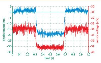
Figure 9.1.1. voltage signal from the capacitive sensor (red line) in comparison with the interferometer signal (blue line). The filter frequency of the sensor was set to 1kHz.
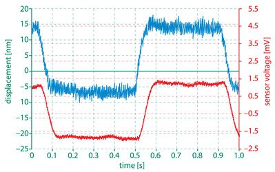
Figure 9.1.2. voltage signal from the capacitive sensor (red line) in comparison with the interferometer signal (blue line). The filter frequency of the sensor was set to 10Hz.
can see that the sensor signal with the 10Hz filter seems to be even better than the interferometer signal. The reason is that higher frequencies do not pass the 10Hz filter of the electronics and thus they are not measured. The sensor seems to be less noisy which can result in a higher accuracy of the full system.
Please note:
The highest positioning resolution requires very stable measurement conditions. The best measurement conditions are:
• A well-grounded environment
• An area far from electromagnetic fields (use shielded cables)
• Vibrationally isolated conditions (an actively damped table is recommended)
• Stable temperature conditions
9.2. Linearity
In an ideal case, the relation between the input signal (signal defining the position of an actuator) and the output signal (realized motion) should be linear. When speaking about systems with integrated sensors, the linearity of the sensor (plus sensor electronics) is an important quality parameter.
Absolute position calculated from sensitivity
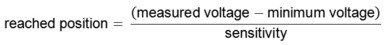
The linearity describes the approximation of the relation between indicated and true position. With the measured voltage (MON) the reached position is to be calculated on the basis of the formula below. The current values for the following calculations are taken from the calibration protocol (e.g. see page 108).

Example number 21
minimum voltage = – 0.007V*
total stoke = 400µm*s
sensitivity = 0.0248 V/µm*
measured voltage = 3.864V
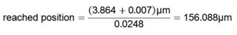
* values are given in the calibration protocol
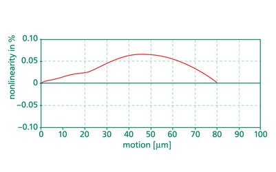
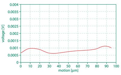
Absolute position calculated from sensitivity with consideration of the non-linearity As already mentioned, the monitor output voltage gives the best values for the current position of the system. Taking into account the measured non-linearity of the positioning system (see calibration curve) the absolute position calculated from the sensitivity should be corrected by the non-linearity.
The deviation of the true actuator position from this linear relation is the non-linearity. This is described by a polynomial function of higher order. In order to calculate the true actuator position on the basis of the measured voltage, the non-linearity must be taken into account.

Example number 22
minimum voltage = – 0.007V*
total stroke = 400µm*
sensitivity = 0.0248V/µm*
non-linearity @157µm=0.037%
measured voltage = 3.864V

= 156,088µm + 148nm
= 156,236µm
*values are given in the measurement report
Taking into account the non-linearity of 148nm at the position of the system of 156µm (MON = 3.864V) had to be corrected to 156.236µm. We determine the linearity of a sensor system in the following way: We operate the piezoactuator with a triangular wave over the full range of motion. The motion of the system will be measured by the integrated sensor and by the laser beam interferometer.
9.3. Repetition Accuracy (Repeatability) – ISO 5725
The repetition accuracy designates the error which arises if the same position from the same direction is approached again and again. In order to achieve a certain position repeatedly the same modulation voltage must be applied. The difference between modulation voltage and monitor voltage is regulated to zero by the electronic controller. The deviation of the different reached positions is indicated by repeatability. In the provided calibration protocol the maximum value of this error is indicated.
Note:
The exact position of piezoelements cannot be accurately represented by an amplifier display due to its resolution. For highly exact positioning requirements it is recommended to supervise the position over the monitor voltage. For this an appropriate digital voltmeter is necessary.
9.4. Dynamic Properties of a Closed Loop System
As stated, all single parts of a closed loop system influence the dynamic properties. This includes the properties of the actuator, of the sensor and the electronic system.
Please note:
When speaking about the properties of the actuator, it means the actuator as integrated into the real experiment. Additional masses or any forces from outside can influence the dynamic properties dramatically. Since we do not know how an individual might make use of our actuators, we did not load additional masses onto the actuators in our experiments. You will find further details about dynamical properties in chapter 5.
The closed loop electronics, utilizing control algorithms (P, PI, PID etc.) also affects the dynamic behavior. Each control system has to be calibrated with the specific actuator. Do not change any modules or actuators of a control system.
For a correct analysis of the dynamical properties, the damping curve and the phase shift over the frequency variation has to be measured. The dynamic function for operating the element should be investigated with respect to the containing frequency. The driving frequency must be smaller than the maximum frequency of the full system. To ensure this, any curve differing from a sine wave form should be analyzed so as not to exceed the containing frequencies. Therefore, a Fourier transform must be made.
Of course this is not very practical.
An approximation in control theory says that the maximum system frequency of a feedback controlled system should be ten times less than the lowest characteristic frequency of the open loop system.
To give a simple impression of what we achieve in closed loop, we did some pure tests with the elements PX100 with strain gauge sensor. The element was driven with a rectangular function of 10Hz with an amplitude of approximately 50% of the full motion. We determined the time in which the controlled system reached an accuracy of 99% and 99,9% of the final position. (see Figure 9.4.1)
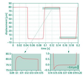
Figure 9.4.1. Response time of a closed loop system PX100 with a strain gauge measurement system
9.5. Calibration Protocol for a Closed Loop System
Each closed loop system to be delivered to our customers is calibrated to reach the optimum values in linearity and repeatability.
This data is shown in the calibration protocol coming with the system.
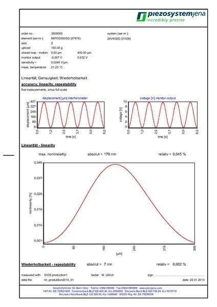
Meaning of parameters
a) Total range of motion
b) Maximum corresponding voltage (voltage at the monitor output, system switched into closed loop operation)
c) Minimum voltage (closed loop) at monitor output
d) Sensitivity (range of voltage related to the full range of motion) (see also formula 9.2.1.)
e) Nonlinearity@200µm = 0.0447% = 179nm
How to calculate the nonlinearity in nm from the data of the calibration protocol:
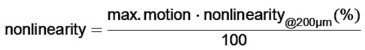

nonlinearity = 179nm
Piezo Principles Topics
- 1) Piezoelectric Effect
- 2) Design
- 3) Properties and Performance
- 4) Static Positioning
- 5) Dynamic Movements
- 6) Lever Transmission Systems
- 7) Simulation of Dynamic Properties
- 8) Closed Loop Systems
- 9) Measurement Systems
- 10) Electronics
- 11) Lifetime and Reliability
- 12) Guidelines for Usage
- 13) High Power Piezos
- 14) Piezo Shakers
- 15) Piezo Shock Generators