3. Properties and Performance
3.1 Expansion
The relative expansion S = l/L0 (without external forces) of a piezoelement is proportional to the applied electrical field strength. Typical values of the ceramic materials are S0.1 – 0.13% (field strength E = 2kV/mm).

S – relative stretch (without dimension)
d = dij – piezo module, parameter of the material
E = U/ds electrical field strength
U – applied voltage
ds – thickness of a single disk.
The maximum expansion will raise with increasing voltage. The relation is not perfectly linear as predicted by equation (3.1). The characteristic curve reflects the inherent hysteresis (see also section 3.2). The maximum expansion that can be achieved by using normal stacks us up to 300 µm. The length of such a stack will be 300 mm!
Typical piezo stacks have motion of 20 – 100µm. For greater expansion, actuators with a lever transmission are superior.
It is possible to combine piezoelectrical elements with mechanically or electromechanically driven systems. So, the motion will be several cm, although the motion will show mechanical play.
3.2 Hysteresis
Because of their ferroelectric nature, PZT ceramics show a typical hysteresis behavior. If voltage is applied in a positive direction and then in a negative direction (bipolar voltage), one can obtain the following curve.

If the voltage is increased, the movement increases. The maximum motion (point A) will be limited by saturation and by the voltage stability (voltage break down) of the ceramic material. If the voltage is reversed, the piezoelement shows a contraction. After removing the voltage, a permanent polarization will remain. Therefore the motion of the piezoelement is not zero (point B). If a definite negative voltage is applied (so-called coercitive voltage; point C) the motion will be zero microns.
The piezoelement will contract when the negative voltage is increased. At the same time the polarization of the dipole in the ceramic begins to change. At point D the polarization of most of the dipoles is changed, so that the element will expand again for increasing negative voltage up to point E. If the negative voltage is reversed, the piezoelement will contract according to the behavior from point A to point B, so point B is again the point which refers to the remaining polarization. By further increasing the voltage (now positive) the element contracts (up to point F) with polarization changes. By further increasing the voltage, the element expands to point A.
The butterfly curve shows that by applying bipolar voltage it is not possible to accurately determine the position of the piezoelement. For example, for the same voltage, the element can be in position G or in position F.
Thus, normally one works with unipolar voltage outside the region of saturation and breakdown and outside the region of polarization changes. So piezoelements show the well-known expansion characteristics.

To get a larger motion, it is possible to work with a negative voltage in the order of 10V to 20V (for multi-layer elements). Therefore we drive our elements with voltages from -20V up to +130V.
Working in that range, you find the typical expansion curve of piezoelements. The typical width of the hysteresis is 10 – 15% of the commanded motion. Working in a small voltage range, the hysteresis is also smaller. This is also shown in the figure 3.2.2. above.
Each piezo element provided by piezosystem jena comes with the measured curve of its hysteresis.
Hysteresis closed loop systems In closed loop systems the closed loop control electronics compares a given or wanted motion (e.g. through modulation input signal) with the actual position measured by the sensor system. Any deviation in both signals will be corrected. Thus closed loop systems do not show hysteresis within the accuracy of the closed loop system. For more details see chapter 8 and 9. OEM elements for industrial applications For piezoelements working under industrial conditions, we recommend working with voltages up to a maximum of 100V in order to achieve the best long term reliability. This is important, especially if the piezoelement must work constantly with maximum expansion (under maximum voltage) over a long time period. Please see also chapter 11 – reliability!
3.3. Resolution
Independent of the hysteresis, the piezoelectrical effect as a solid state effect has a very high resolution. A piezo element PX 38 from piezosystem jena was tested in an interferometer and a motion of 1/100nm was detected. Therefore the resolution is limited by the noise characteristic of the power supply. Our power supplies are optimized to solve this problem (please see also section 9.1. and 10.1.).
Example number 6
Our plug in PC card has a voltage noise of < 3mV at the output. Relative to 150V maximum voltage this is a value of 2 · 10-5. Operating a piezoelement with a maximum expansion of 20µm, the mechanical noise of this system will generate oscillations in the order of 0.4mm.
You are invited to speak with our team about various power supplies for their specification!
We have several different voltage amplifiers (power supplies). A compact 3 channel supply, or power supplies in 19 inch eurosystem. A very interesting supply is our plug in PC card, which controls up to 3 different piezoelements directly from the PC.
3.4 Polarity
In general our piezoelements work with a positive polarity. A minimum reversal voltage on the order of 10 % of the maximum voltage (for example -10 V for 130 V multi-layer elements) will increase the total expansion. A higher reversal voltage is not recommended because of depolarization effects. On request, it is possible to construct the elements with positive or negative polarity.
3.5 Stiffness
A piezoelectrical actuator can described by a mechanical spring with constant stiffness. The stiffness is an important parameter for characterization of the resonant frequency and generated forces.

The stiffness is proportional to the cross section A of the actuator. The stiffness decreases with an increasing actuator length L0. In reality the dependence is more complicated. The stiffness is also related to other parameters, e.g. how the electrodes are connected.
When the electrodes are not connected, there is no way for the energy to be dissipated; therefore in this case the stiffness has its largest value.
Stiffness
However, formula 3.5.1 does not describe the reality exactly enough. Depending on the kind of operation (static, dynamic operation) and the environment influence (load, electrical parameters of the electronic supply, small or large signal operation) the stiffness can vary up to a factor of 2 or more. Thus using formula 3.5.1 can give only a rough estimation of the expected properties of the piezoelements. Please consider, the electrical capacitance measured for piezoelements with small signals can increase up to 2 times when operated with large signals (under full motion).
Example number 7
An actuator with a cross section of 5 x 5 mm2 and an active length of 9 mm has a stiffness of cT1E = 120 N/µm. With the same construction (cross section, material) but double the length (18 mm), the stiffness will be a half stiffness (60 N/µm). If an actuator with a cross section 4 times larger (for example 10 mm x 10 mm, length 18mm) is used, the stiffness will be 240 N/µm.
3.6. Thermal Effects
Temperature variation is an important factor in the accuracy of a micropositioning system. The thermal expansion coefficient of stainless steel for example, is about 12·10-6 K-1. Imagine a cube of 10x10x10 mm3 – at temperature change of only 1K leads to an expansion of more than 0.1µm in each direction. With these relationships in mind, it is easy to understand that the calibration of piezoelements with integrated measurement systems depends on the temperature. If the operating temperature is different from the temperature during calibration, errors will occur.
When speaking about temperature coefficients of piezoelements, we must consider three effects:
a) The temperature behavior of the piezo ceramic material depends on the type of ceramic material. Piezo stacks operating with high voltages show a positive temperature coefficient on the order of αHV = (7 – 10)·10-6 K-1.
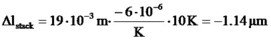
Multi-layer stacks show a negative temperature coefficient of αNV ≈ -6·10-6 K-1 in the range up to 120°C.
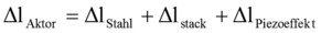
The thermal length variation of a whole short circuit actuator (e.g. series P, PA, PAHL) is the sum of the thermal expansions of the piezo ceramic and of the metal parts of the actuator.

Δltherm = thermal expansion of the whole actuator
Lpiezo = length of the piezo stack
Lmetal = length of the metal housing
αpiezo = temperature coefficient of the piezo ceramic
αmetal = temperature coefficient of the metal housing
ΔT = temperature differential
Example number 8
If the temperature around a PA 16 actuator changes from 20°C to 30°C the length difference at a voltage of 150V (full stroke) is
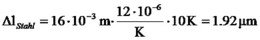
b) The piezo effect itself also depends on the temperature. In the range <260K, the effect decreases with falling temperature with a factor of approximately 0.4% per Kelvin.
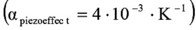
In the region of liquid nitrogen (T1 ca. 77 K), the expansion due to the piezoeffect will be around 10 – 30 % of the expansion at room temperature (T0). Assuming the relation between the change of the piezo electrical expansion with temperature is linear, it can be expressed as:
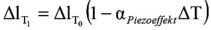
ΔlT1= expansion at T1
ΔlT0 = expansion at room temperature
ΔT = T0 – T1
αpiezoeffect= temperature coefficient of the piezo effect
In the range of 260K to 390K the change of the piezoeffect can be neglected.
Example number 9
To estimate what maximum stroke by a PX 100 at -195°C (liquid nitrogen) can be expected, the temperature difference to -10°C should be calculated. So it is ΔT=185K. The estimated stroke is around 25µm.

Figure 3.6.1. Example of temperature dependence of multilayer ceramic Lpiezo=18mm at room temperature.
c) The ferroelectric hysteresis decreases with falling temperature. The hysteresis of piezoelectric actuators is a result of the ferroelectric polarization (see also chapter 3.2.). At very low temperatures of four Kelvin for example, there are almost no changes of the electrical dipoles (domain switching) and so there is very little hysteresis.
In the region of room temperature, the influence of temperature variations to the hysteresis can be neglected.

But please take into account:
Although the piezo effect decreases with falling temperature, piezoelectric actuators principally can work at very low temperatures – down to the temperature of liquid He (4K).
If you want to work in a low temperature regime, please tell us about this fact, so we can prepare the actuator for this temperature region.
Stages
The temperature behavior for elements integrated into a lever design depends on both the temperature effect for the piezoelement and the behavior of the stage. It may differ from the behavior described above for the piezoelement itself. Because of the different constructions used for different stages a general rule cannot be given.
Closed loop stages
Please take care to use closed loop stages at near the temperature at which they were calibrated. Only at the temperature of calibration, piezoelements show the best accuracy.
3.7 Capacitance
As mentioned a stack actuator consists of thin ceramic plates as dielectricum and electrodes. This is a system of parallel capacitors.
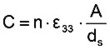
n – number of ceramic plates, ε33 – dielectric constant, A – cross section of the actuator or the ceramic plates, ds – thickness of a ceramic plate.
Example number 10
A multi-layer stack with an (active) length of 16mm, a cross section of 25mm² and a thickness of the ceramic plates of 110µm consists of approximately 144 plates. With a relative dielectricity of εr = 5400 one yields a capacitance of the actuator of approximately 1.6 µF (see formula 3.7.1).
Capacitance of multi-layer actuators – capacitance of high voltage actuators
Let us consider the following comparison:
Example number 11
A multi-layer actuator (index 1; parameter see example number 10) should be replaced by a high voltage element with the same length (index 2). For simplicity, both stacks consist of the same material. Refer to formula 3.7.1. The thickness of the ceramic plates of the high voltage actuator is 5 times larger (ds2 = 5 ·ds1) so the number of plates is 5 times lower (n2 = 1/5 ·n1).
Thus the capacitance of the high voltage actuator is much lower than the capacitance of the multi-layer actuator C2 = C1/25.
The operating voltage for the same expansion is lower for multi-layer stacks. But the capacitance is increasing quadratically.
Please note:
Because of the higher capacitance of low voltage multi-layer stacks, these actuators need much more current in dynamical applications. The current can be neglected for static and quasi-static motions.
Please note:
The piezoelectrical properties of actuators are not constant as assumed in simple descriptions. Most of the parameters depend on the strength of the internal field. Most of the values given in the literature are for low electric fields. These values can differ for high electric fields. As an example, the capacitance for high voltage operation is nearly twice that given for low voltages.
3.8. Drift/Creep (Open Loop Systems)
Another characteristic of piezoelectrical actuators is a short dimensional stabilization known as creep. A step change in the applied voltage will produce an initial motion followed by a smaller change in a much longer time scale as shown in the figure 3.8.1.
As one can see, the creep will be within 1% to 2%, in a decade of time. The creep depends on the expansion Δl, of the ceramic material (parameter of the material γ), on the external loads, and on time. The dependence of the creep can be shown also as a logarithmic dependence of time.
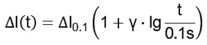

Figure 3.8.1. Creep of a PU 40
In this case we reach a value for γ ≈ 0.015. The value of γ depends on the material, the construction and the environmental conditions (e.g. forces).
When the motion (voltage) is stopped, after a few seconds, the creep practically stops.
Repeatability for periodical signals
When working with periodic signals, the repeatability of a position will not be deteriorated with creep. Because of the strong time dependence of the motion, creep occurs in all oscillations in the same order.
In the figure we have shown a periodic oscillation of a mirror mount PSH. The power supply is a normal power supply controlled by a function generator. The full tilting angle is approximately 380 arcseconds. In the picture there is a section of only 10 arcseconds (from -302“ up to -312“). It can be seen that the repeatability is better than 0.1“ which is better than 0.03%.
As a result of this experiment, we have reached a high repeatability within the system without a closed loop control. For such experiments the repeatability is only determined by the quality of the power supply.

3.9 Working Under Vacuum Conditions
The piezoelectrical effect, in general, works also under vacuum conditions. The only problem arises from the outgassing of the materials used.
For protection of both people and the piezoelectrical actuators from electrical breakdown, the actuators are insulated using rubber materials. However, these materials exhibit bad outgassing characteristics. That is why piezoelectrical actuators for vacuum applications are produced from materials (for example, adhesives) with low outgassing characteristics. We do not use any rubber materials. Consequently the outgassing is extremely low.
We can offer most of our elements with vacuum options.
Please note:
In the pressure region between 0.01Torr, up to 100Torr the gases used have a very low insulating behavior. If piezoelements with vacuum options (prepared with materials with very little outgassing) are used in this pressure region, the elements can be damaged because of electrical breakdown. Piezoelectrical actuators prepared for vacuum applications should not be used in this pressure region. For safety reasons, piezoelements with vavuum options must not be used in environments where someone can touch the contacts.
Example number 12
The piezoelectrical driven optical slit from piezosystem jena was especially prepared for vacuum applications. Up to a pressure of 5·10-9Torr, no influence of outgassing of the piezo element was detected. The piezo elements were not heated.
Heating, baking out of piezoelements.
Piezoelements from piezosystem jena can be baked out up to 80 °C (175°F) without problems. Elements with special preparation can be baked out up to 150 °C (300°F).
3.10 Curie’s Temperature
The ferroelectric nature, and so the piezoelectrical properties, will be lost if the material will be heated over the Curie point, 150°C. So it is important to work below the Curie temperature.
The Curie temperature is dependent on the material. Normally, multi-layer actuators have a Curie temperature of 150°C. High voltage actuators have a Curie temperature of 250°C.
In special cases it is possible to work with other ceramic materials with varied Curie temperatures.
If a piezoceramic is heated (for example by dynamical motion) up to the Curie temperature, thermal depolarization will occur. If temperature parameters are not given we recommend working in temperatures up to Tc/2 (normally up to 80°C).
If materials become depolarized, the piezo-effect is lost. However, the application of a high electrical field to the actuator can restore it. Thus, special piezoelectrical materials can be annealed in the vacuum chambers.
The heating of piezo actuators can be ignored when working under static and quasi-static conditions. It should be taken into account for dynamical applications (see section 5).
Piezo Principles Topics
- 2) Design
- 10) Electronics
- 14) Piezo Shakers