Resolution:
In the catalog a resolution of e.g. 2 nm is specified. How can I check this resolution?
Upon customers’ request, and because of the predetermined digit numbers, some of our amplifiers (e.g. NV 40/1 CLE) just display two digits after the comma. Thus, the amplifier can only display the motion of the system in 10 nm-steps. This doesn’t mean that the actuators show a worse resolution than the value given in the catalog. It means that you can’t see it on the display.
The monitor output must be used in order to check the accurate resolution. Over the MON-voltage and the sensivity (see calibration protocol) the exact motion, and hence the resolution, can be determined.
Digital Resolution:
I have a digital amplifier EVD50 and want to control the piezo stage by PC. How do I get to know the minimum step size?
The minimum step size (resolution) is determined by the stroke of the actuator and the bit resolution of the serial interface, and can be calculated by dividing the full stroke by the 20 bit resolution of the interface (1,048,576).
In the case of a PX 400, the resolution is calculated by 400 µm divided by 1,048,576, which results in a resolution of 0.4 nm.
Device Designation – Suffixes:
What do the different suffixes mean, e.g. regarding the amplifier “ENV 300 nanoX SG”
| Suffix | Example | Abbreviation for | Fits to actuators… | Examples for actuators |
| SG | ENV 300 SG | strain gauge | … with integrated strain gauge sensor | PA 8/14 SG, PU 40 SG, MIPOS 250 SG |
| CAP | ENV 300 CAP | capacitive | … with integrated capacitive sensor | PZ 38 CAP, PXY 100 CAP, MIPOS 250 CAP |
| CLE | ENV 300 CLE | closed loop external | … with external capacitive or strain gauge sensor | PA 8/14 SG – external PZ 38 CAP – external |
| nanoX | ENV 300 nanoX | nanoX | … of series nanoX, nanoSX, nanoSXY and PSH – with bidirectional drive | nanoX 200, nanoSX 400, nanoSX 400, PSH 15/1 nanoMIPOS 400 |
| nanoX SG | ENV 300 nanoX SG | nanoX strain gauge | … of the series nanoX, nanoSX, nanoSXY and PSH with integrated strain gauge sensor | nanoX 400 SG, PSH 35 SG |
| nanoX CAP | ENV 300 nanoX CAP | nanoX capacitive | … of the series nanoX, nanoSX, nanoSXY and PSH with integrated capacitive sensor | nanoX 200 CAP, nanoSXY 400 CAP, nanoMIPOS 400 CAP |
| nanoX CLE | ENV 300 nanoX CLE | nanoX closed loop external | … of the series nanoX, nanoSX, nanoSXY and PSH with external capacitive or strain gauge sensor | nanoX 200 CAP- external |
High Frequencies in Closed Loop Mode:
Can actuators equipped with strain gauges be operated with high frequencies in closed loop mode?
No, the highest frequency actuators with strain gauges can reach is around 30 Hz.
The bandwidth of the sensor pre-amplifier is 5 kHz, nevertheless the control electronics still need time to process the signals and to correct the actuator´s position.
A frequency of about 100 Hz can be reached by optimizing several parameters of the control electronics. This is done by piezosystem jena within the context of a special calibration.
Cables:
Which kinds of cables are used?
piezosystem jena uses cables with high voltage signal isolation and shielding protection. UL certification is available. For vacuum applications, the standard cable comes with Teflon-Polyimide insulation material for non out-gassing . Upon request, Kapton cable is also available.
Cables:
How long are the cables?
The standard cable length is 1 m for open loop actuators. In closed loop actuators, the cable lengths are 1.6 m for capacitive systems and 1.2 m for strain gauge systems. Inside a vacuum, the cable length is limited by 0.6 m. The outside cable length is 2 m. Special cable lengths are available upon request.
Calibration:
What and when is the calibration procedure?
Each closed loop system must be calibrated. The travel range of the piezo actuating system must be adjusted to the voltage range of the amplifier. The calibration is done by a high resolution interferometer set up. A calibration protocol is provided with each calibrated system. If the customer doesn’t specify parameters, such as added load, step size, frequency, and travel range, piezosystem jena will do a standard calibration procedure.
piezosystem jena warranties for one year the accuracy of the calibration. Our experience shows, that the calibration is stable over years. If it is necessary, piezosystem jena can recalibrate your system as well.
All changes made to the system, e.g. cable modification, installation setups, and temperature differences, affect the accuracy and may change the values of calibration given by the protocol.
Lifetime and Reliability:
Which specifications can be made regarding lifetime and reliability of piezo actuators?
For static applications:
- see catalog (piezoline, chapter 11): “Lifetime – reliability”
For dynamic applications:
- see catalog (piezoline, chapter 11): “Lifetime – reliability”
Because the parameters differ from application to application, it is not possible to calculate the lifetime for dynamic applications using any universally valid formula.
Many customers have used our piezo actuators in static, dynamic, and also highly dynamic applications for many years without reporting a failure, e.g.:
| Application | System In Use |
|---|---|
| special microscopes | for 15 years |
| cameras | for 10 years |
| lithography | for 10 years |
| laser technology | for 10 years |
| print technology | for 7 years |
| rapid prototyping | for 5 years |
| microscopy | for 5 years |
| wafer inspection | for 5 years |
MIPOS Series – Lens Flex-Adapters Improve Handling and Compatibility:
What is important to know about vacuum applications?
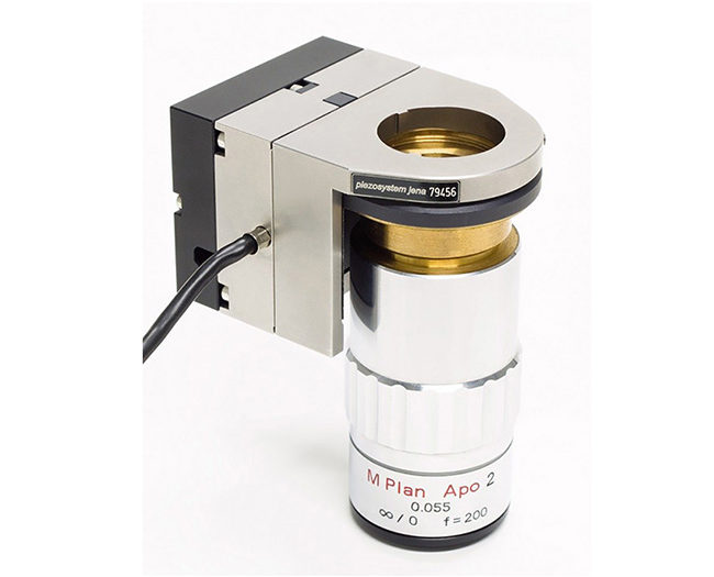
piezosystem jena has made major improvements to its well established MIPOS series by introducing a Lens Flex-Adapter mechanism. This technology allows the easy and fast exchange of microscope objectives compatible with a variety of thread sizes from Zeiss, Leica, Nikon, Olympus, and others.
The new Lens Flex-Adapter makes it possible to combine objectives and microscopes from different manufacturers with ease.
The Lens Flex-Adapter mechanism makes the interchange of objectives both simple and accurate due to the use of an exchangeable thread adapter in sizes ranging from W0.8 x 1/3” up to M32 x 0.75. Its innovative design avoids extra forces while the objectives are being changed by not allowing the material to merge. Lens Flex Adapters are available individually as well as a set of six thread type adapters for the the combination of different microscopes and objectives.
The MIPOS series actuators were developed for the fine adjustment of micro objective lenses. They provide a wide range of motion from 20 µm up to 500 µm. Their position accuracy and resolution are extraordinarily high. The MIPOS is the perfect upgrade for modern microscopes.
Key Features:
- Focus range up to 500 µm
- Easy assembling and disassembling due to the Flex-Adapter mechanism
- Available Lens Flex Adapter – thread types:W0.8×1/36” (RMS), M25x0.75, M26x0.75, M26x1/36”, M27x0.75, M32x0.75
- Parfocal Spacer Rings for tube extension
- Compatible with both standard and inverted microscopes
Pin Connection:
What is the pin connection for the actuators of piezosystem jena?
Please find an overview about pin connection in our Downloads section.
Resonant Frequency:
Is it possible to operate the piezo actuator at the specified resonant frequencies?
- In principle, we recommend that the piezo system be operated within 80% of the maximum resonant frequencies. Higher operating frequencies can destroy the piezo actuator unless the actuator is operated at a value significantly less than 10% of the motion.
- The resonant frequency found in the data sheet most commonly signifies the resonant frequency without a mass. Every additional mass decreases the resonant frequency.
- High current are often needed for the dynamic operation of piezo actuators. The higher the required operating frequency, the higher the current needed will be. The current can’t increase infinitely. This factor sometimes limits the operating frequency.
RoHS Directive:
Does piezosystem jena comply with the RoHS directive?
All products offered by piezosysem jena fulfil the requirements of the EU directive 2011/65/EU.
Also refer to the declaration in our Downloads section
Softstart:
Can “softstart” be deactivated?
Yes, if required the softstart can be switched off. Deactivating the initializing procedure is recommended for applications where the piezo actuator is operated daily or where the actuator’s full stroke would cause clashes in the application set-up.
Switching off the softstart is realized via software or by changing the jumper position. Please inform us about your requirements when ordering.
Softstart:
Why do I need “softstart”?
The inverse piezoelectric effect is a solid state phenomena that results from the arrangement of the polarized unit cells depending on the applied electrical field. During long term storage, depolarization may occur so that the dielectric field strength within the multilayer piezo ceramic decreases.
An abrupt application of high voltage may cause the piezo actuator to short circuit. To avoid this risk, the automatically launching softstart procedure re-polarizes and refreshes the piezo ceramic.
Softstart:
What is “softstart”?
Softstart is a procedure that initializes your complete system consisting of a piezo actuator and an amplifier. After powering on, the amplifier starts to apply voltage until it has reached the full voltage range, and then cycles it back to zero. This way the piezo actuator moves from the minimum position to the maximum and back.
Piezo actuators in the nanoX, nanoSX, nanoSXY, and nanoMIPOS series, as well as some of the piezo tilting systems, start their cycle from the middle position to the maximum and then to the minimum (zero position). This cycle takes approx. 3 seconds. After this process the system is ready for operation.
Special Calibration:
What is special calibration?
A special calibration can be either necessary (if the customer’s application is quite different from the assumptions of standard calibration) or preferable (if the customer runs the same function every time and the standard calibrated system is too slow). If system is specially calibrated, this system will mostly work for that one particular application.
Special calibration is necessary if:
- A piezo will be mounted for an unusual way of motion (e. g. movement of MIPOS horizontally)
- The customer wants to have a motion range between those of open loop and closed loop (usually closed loop motion starts at about 10% of open loop motion). Lower and upper motion reserves are different than 10% of the open loop motion
- There is a different mass added, a mass outside of the center of the piezo, or a mass with an unfavorable shape (long levers) which significantly change the dynamic behavior of the system.
Special calibration is preferable once a system needs to be tuned in order to be faster.
Any customer can set the PID-values of the controller themselves if they use digital amplifiers (EVD 50 CL, 30DV50). Digital amplifiers enable the customer to easily change many calibration values. Please also look at our ASC-function. The change of any calibration values of analog amplifiers (e. g. NV 40/3 CLE) can only be realized at piezosystem jena.
Mirror Mounting:
How is the mounting of a mirrors on the top plate of the mirror tilting system PSH done? Are there any additional connectors necessary?
The mounting of the mirrors is often done by our customers themselves. In most cases, the mirror is glued to the top of the PSH mirror tilting system. For the PSH 4/1 system there is also the possibility of using a mirror holder.
Standard Calibration:
What is standard calibration?
All closed loop systems (positioning systems integrated with length measuring sensors) are calibrated. Calibration is done in 3 steps:
- Setting of the 0-point of the MON-output according to about 10% of open loop motion
- Adjusting of the gain of MON-voltage according to closed loop motion
- Setting of the PID-values of the controller to achieve the fastest possible response of the piezo with almost no overshooting
- piezo is used in its natural direction of motion
- dynamic worst case is applied to MOD-input (input jump with full closed loop travel)
- depending on the range of motion and the design of the piezo, a particular mass is added (e.g. MIPOS with 100 µm travel range is calibrated with an additional load of 135 g; MIPOS with more than 100 µm travel range is calibrated with an additional load of 160 g)
The calibration is done under this worst case scenario, so that it will work for all other (more likely) applications. This is assuming that all the variables are close to specification (direction of motion and added mass). However, this calibration might have too slow of a response time for particular applications. In these cases, piezosystem jena offers the possibility of special calibration.
Types of Connectors:
Which kinds of connectors are used?
Voltage
- LEMO 0S.302 for standard open loop and SG closed loop non external pre-amplifier
- LEMO 0S.302 for closed loop external pre-amplifier and CAP closed loop non external pre-amplifier
- ODU L-series 3pin for all nanoX-based piezos
- D-Sub 15 digital version
Sensor
- LEMO 0S.304 for strain gauge non external pre-amplifier
- LEMO 0S.650 for capacitive feedback sensors non external pre-amplifier
- ODU L-series 4pin for external pre-amplifiers (either SG or CAP)
- D-Sub 15 digital version
System Configuration:
Which information are important to find the right system for your application?
Our sales team will aid you in finding a fitting system. In order to do so, it is necessary for the team to know the intended application.
The following information will help the sales team find the right actuator:
- motion
- required forces (at which motion?)
- moving direction
- number of axes
- load
- load allocation (if possible with a picture or a draft)
- required resolution, repeatability, and nonlinearity
- Is a special position stability required?
- static application: How long the actuator will hold the same position?
- dynamic application: Is a fast step response required? Which typical steps?
- oscillation: triangle, rectangle, and/or sine?
- Which environmental conditions will the application take place in? (humidity, temperature, vacuum/cryogenic)
- Which forces will affect the piezo? (lateral / motion of the piezo e.g. on a linear stage)
Temperature Range:
What is the correct temperature range for using piezoelectrical actuators?
piezosystem jena’s piezo electrical ceramics have a Curie temperature of approximately 150°C. The full piezo electrical effect of the ceramic can only be guaranteed up to 80°C. Higher temperatures can reduce the polarization effect but usually do not damage the ceramic.
The piezo electrical effect can be used down to nearly 4 Kelvin, but the effect drops down to nearly 10% of the effect at room temperature. piezosystem jena ceramics are specified for a temperature between -20°C and 80°C. All systems are calibrated at a temperature of 22°C. Fluctuations in temperature affect the accuracy of the system.
Please ask us for more information if your application involves a lower or higher temperature range e.g. in ultra high vacuum applications.
Please note that the temperature effect can be more important for the material surrounding the ceramics, such as the stainless steel casing of some stack type actuators, than for ceramic itself.
Cryogenic Application:
What is important to know about cryogenic applications?
The piezo effect itself depends on the temperature. The effect decreases with decreasing temperature at a rate of approx. 0.4% per Kelvin. In the temperature range of liquid nitrogen (ca. 77 K) the expansion due to the piezo effect will be about 20-30% of the expansion at room temperature.
In principle, piezoelectrical actuators can work at very low temperatures, such as the temperature of liquid Helium (4 K).
All systems ordered with the vacuum compatible option can be used in the cryogenic region. Please note that the original motion of the PZT is reduced when used at low temperature.
Open Loop Mode =100% Motion. Closed Loop Mode = 80% Motion:
Why can I reach in closed loop operation only 80% of the motion in open loop operation?
When piezo actuators with a measurement feedback system are operated in closed loop, the full motion will not be available.
The control system needs a voltage buffer to reach the specified critical limits of the zero point and the maximum motion in the specified control response time. The decrease of the motion is approx. 20% of the overall value.
CAP versus SG
What are the differences with closed loop systems between capacitive feedback sensor and strain gauge feedback sensor?
What are the differences between closed loop systems with a capacitive feedback sensor and those with a strain gauge feedback sensor?
Piezo systems with capacitive sensors have better resolution (sensor resolution 1 nm), non-linearity (typ. 0.05%), and repeatability. Capacitive systems are the best choice for applications that require good long time stability. Normally these sensors are arranged in the actuator between the fixed-point and the drive side. Thus, they register the whole mechanical assembly and control the position with high precision.
Strain gauges provide a resolution of up to 35 nm. Their advantages include a small size and large bandwidth of up to 5 kHz. They are a good option for applications with resolutions above 35 nm. A disadvantage is the local configuration of the measurement bridges that do not allow all drift effects to be measured. This reduces their capability to provide high of a long term stability.
Results:
CAP – advantages
- high measurement accuracy, optimal for long time applications
- good values regarding non-linearity, repeatability, and resolution
- cross motion is compensated for e.g. at XY systems
CAP – disadvantages
- often the actuators have a bigger footprint
- bandwidth max. of 1 kHz
- more expensive
DMS – advantages
- very compact size
- big bandwidth of up to 5 kHz
- more cost effective than the CAP
DMS – disadvantages
- no high long term stability
- resolution not better than 35 nm
- cross motion is not compensated for
Piezo Principles Topics
- 1) Piezoelectric Effect
- 2) Design
- 3) Properties and Performance
- 4) Static Positioning
- 5) Dynamic Movements
- 6) Lever Transmission Systems
- 7) Simulation of Dynamic Properties
- 8) Closed Loop Systems
- 9) Measurement Systems
- 10) Electronics
- 11) Lifetime and Reliability
- 12) Guidelines for Usage
- 13) High Power Piezos
- 14) Piezo Shakers
- 15) Piezo Shock Generators
