2. Piezo Design
2.1 Stacked Design
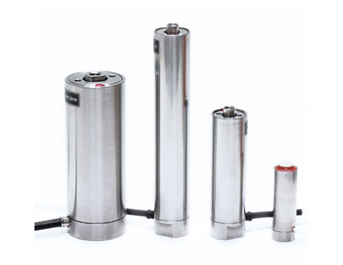
Piezo stacks consist of a large number of contacted ceramic discs. The electrodes are arranged on both sides of the ceramic discs and are connected in a parallel line as shown. Piezostacks are also called actuators, piezoelectrical actuators or piezoelectrical translators.

The maximum motion caused by the inverse piezoelectrical effect depends on the electrical field strength and saturation effects of the ceramic material. The breakdown voltage of the ceramic limits the maximum field strength. Normally, piezo stacks work with a maximum field strength of 2 kV/mm. This strength can be reached with different voltage values if used with different thickness of the single ceramic plates.
Example number 2
An actuator consists of 20 ceramic plates. The thickness of one plate is 0.5 mm. The total length of the actuator is 10 mm. The actuator will reach a maximum expansion of approximately 10 µm for a voltage of 1000 V (high voltage actuator).
For plates with a smaller thickness the maximum voltage will be less. Modern multi-layer actuators consist of ceramic laminates with a thickness of typically 100 µm and works at voltages typically 130 V high.
Example number 3
A multi-layer actuator with a total length of 10 mm consists of 100 disks with a thickness of 100 µm. The stack will reach nearly the same expansion of 10 µm with a voltage of 130 V. However, it should be mentioned that the capacitance of this multi-layer actuator is much higher than the capacitance of high voltage devices. This can be important for dynamical applications (see also section 3.7: Capacitance, section 5: Dynamic properties and chapter 10: Electronics).
It is more complicated to produce multi-layer piezoelectrical actuators. Because of the advantage of the lower voltage, some companies are developing so called monolithic actuators. This means, the green sheet ceramic will be laminated with the electrode material. In this way, the full actuator will be made as one system. So the actuator will have the equivalent parameters (for example a high stiffness) of a solid ceramic material. Such monolithic actuators are provided by piezosystem jena.
Piezostacks with and without mechanical pre-load
Because of their construction, the compressive strength of piezo stacks is more than one order of magnitude larger than its tensile strength. Mostly, the glue used to laminate the actuators, determines the tensile strength.
When actuators are used for dynamical applications, compressive and tensile forces occur simultaneously due to the acceleration of the ceramic material. To avoid damage to the actuators, the tensile strength can be raised by a mechanical pre-loading of the actuator. Another advantage of the pre-load is better stability of the actuators with a large ratio between the length and the diameter. Normally the mechanical pre-load will be chosen within 1/10 of the maximum possible loads. You can find more information in sections 4 and 5 of the piezoline.

We recommend using a pre-loaded actuator from piezosystem jena when:
• tensile forces can affect the actuator
• they are used in dynamical applications
• shear forces (shear strain) affect the actuator (external forces perpendicular to the direction of motion

Actuators without pre-load should be mounted on the end faces. This can be done using adhesive or threads in the bottom of the housing. You should not apply shear, cross-bending or torsional forces to the actuator. Clamping around the circumference is not allowed. External forces on the top of the actuator should mainly be in the direction of expansion central to the end faces.
2.2 Tube Design
For this actuator there is the used transversal piezoelectrical effect. The tubes are made from a monolithic ceramic; they are metalized on the inner and outer surface. Normally, the inner surface is contacted to the positive voltage. If an electric field is applied to the tube actuator, a contraction in the direction of the cylinder’s axis, as well as a contraction in the cylinder’s diameter, results in a downward motion. If the outer electrodes are divided, the tube can work as a bimorph element. In this way, it is possible to reach a larger sideways motion. Piezotubes are used for mirror mounts, inchworm motors, AFM (atomic force microscopes) and STM microscopy.

Example number 4
Consider a tube actuator with a diameter of 10mm, a wall thickness of 1mm and a length of 20 mm. The maximum operating voltage is 1000 V. So, the applied field strength is 1 kV/mm. The transversal piezoelectrical effect shows a relative contraction of approximately 0.05 %. For the length of 20 mm, one will get an axial contraction of 10 µm. Simultaneously the circumference of 31.44 mm will be shorter by 15 µm. This is related to a radial contraction of 4.7 µm.
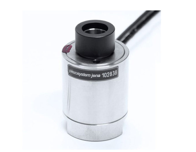
2.3 Ring Actuators with Central Hole
Ring actuators are build similarly according to multi layer stack actuators. But with their free hole (Figure 2.3.1) making it possible to perform radiation or small components. This type of actuator is mainly used in the field of beam manipulation and laser resonators. The mechanically prestressed versions of these actuators can be used dynamically.

2.4 Bimorph Elements
These elements are made from two thin piezoelectrical ceramic plates mounted on both sides with a thin substrate. The principle is similar to thermo bimetal circuits.
Applying opposite field strength to the ceramic plates, one plate shows a contraction, the other will expand. The result is bending in the order of sub-mm up to several mm. Bimorph elements use the transversal piezoelectrical effect (see also section 4), the working piezoelectrical module is the d31 coefficient. Piezoelectric bimorph elements have resonant frequencies from 100 – 300 kHz. Because they show a large drift (creep) while doing static work (because of shear stress in the layers) they are often used in dynamic applications. Because of their construction, they have a low stiffness and they cannot make a parallel motion (almost circular).

Serial bimorph
Both piezoelectrical plates are polarized in opposite directions. A voltage is applied to the electrodes on the ceramic plates on the outside. If a voltage is applied and the plate shows a contraction, the other will show an expansion.
Parallel bimorph
A metal plate middle electrode is between the two ceramic plates. The polarization of both ceramic plates is in the same direction. The bending of this bimorph will be reached by applying opposite voltages to the electrodes. Because of the metal plate in the middle, these bimorph elements have a higher stiffness.
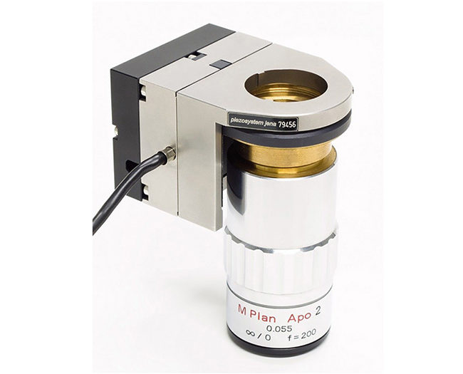
2.5. Hybrid Design
For many applications it is necessary to have a motion on the order of 50 µm – 300 µm (for example fiber coupling problems). To use stacked actuators for a motion of 300 µm, one needs a translator with a length of 300 mm, independent of whether you are using high or low voltage stacks. The high capacitance is another disadvantage of such large stacks. Because of the inhomogeneous expansions of the ceramic plates, the top plate of the stack will always show a slight tilting motion.
That’s why bimorph elements are not suited for parallel motion or force generation.
piezosystem jena has developed a hybrid piezoelectrical element for parallel motion with high accuracy. A lever design of the construction gives very compact dimensions. We have developed the hybrid elements for three dimensional motions. Since we use solid state hinges, mechanical play does not occur. The working principal is shown in the figure below.

The flex-mount points A,B,C and D are solid state hinges. piezosystem jena uses a monolithic design; the motion is achieved by bending these flex-mounts.
Because of the rectangular design and the thread holes, it is very simple to combine these elements with normal mechanical stages. The advantage is a much higher accuracy and an excellent resolution of the motion. Because most of these elements have an integrated pre-load, they are suited for dynamical motions (see also section 6: lever transmission!).
Please note the following advantages of piezoelectrical driven stages:
When a piezo element is working, no manual forces are required to position the stage. Using only mechanical positioning systems, the position cannot be held if the external forces are removed.
These positioning problems (for example for fiber coupling) can be avoided by using piezoelectrical elements.
Example number 5
The piezo elements miniTRITOR 38 from piezosystem jena generates a rectangular motion of 38 µm in x, y and z direction. Integrated solid state hinges with parallelogram design provide parallel motion without any mechanical play. The dimensions are 19 mm x 19 mm x 16 mm. Another element is the piezo element PX 400. This element gives a motion of 400 µm; the dimensions are 52 mm x 48 mm x 20 mm. This element is also suited for dynamical motion.
For comparison, a piezo stack with 400 µm motion would need at minimum a length of 400 mm.
Piezo Principles Topics
- 2) Design
- 10) Electronics
- 14) Piezo Shakers